

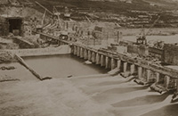


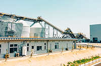
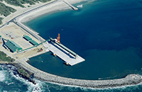


caisson
technology
technology
harbor technology
/green technology
- Mud pressurization (DK) shield method
- Double-O-Tube (DOT) shield method
- Developing Parallel Link Excavation (DPLEX) shield method
- Jack-driven Developing Parallel Link Excavation (J-DPLEX) shield method
- Detaching And Proceeding to dig Piping (DAPPI) construction method
- Mud pressurizing propulsion method
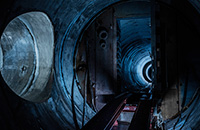
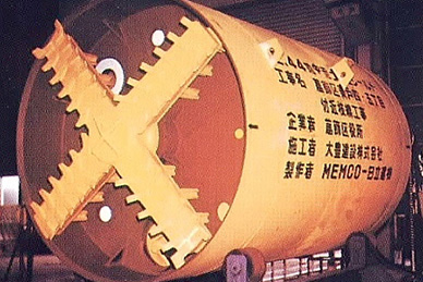
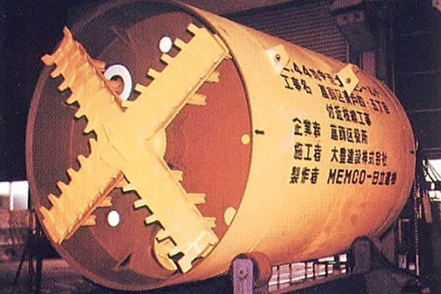
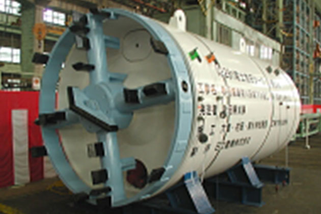
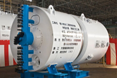
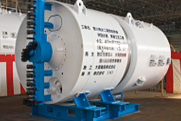
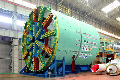
Civil Engineering Business: Mud Pressurization (DK) Shield Method
The representative shield construction method aimed at stabilizing the cut face with mud
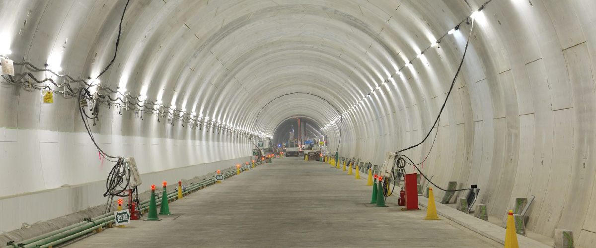
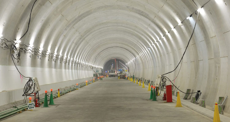
Outline of the construction method
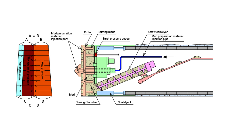
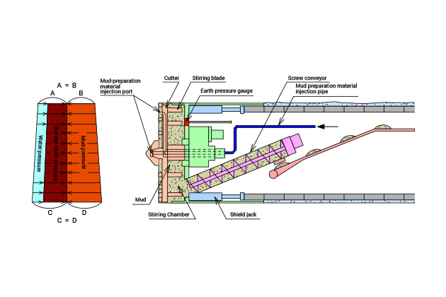
With the mud pressurization shield method, the gravel cut using cutters are transformed into mud in order to manage excavation by controlling mud pressure to stabilize the cut face. It is the representative construction method of muddy soil pressure type shield method.
Characteristics of the construction
method
By adding the adequate amount of mud control agent at the proper concentration to the sand layer, sand gravel layer, silt clay layer, water sand layer, and alternate layers, they can be converted into mud having plastic flow capability and impermeability, which can be applied to a wide variety of soil properties. Moreover, the high-grade cut face stabilization system allows for measurement of the density, moisture ratio, and amount of removed earth in real time, thereby realizing stabilization of cut faces ensuring its accurecy.
Since cut faces are retained by mud even in the case of work in a small overburden zone not larger than 1D (D: external diameter of shield), safe work is ensured. Safe, secure work is realized even under severe conditions.
In the excavation experiment in which 0.7 MPa was applied as the maximum water pressure, excavation performance under high water pressure environment has been confirmed, which makes this method applicable to projects at high depth/water pressure where groundwater pressure is applied.also, high water pressure can be handled by using a pump to pump out the soil.
Our Works
-
- Work name
- Branch Line Work in Aoto 4/5-chome, Katsushika-ku
- Client
- Katsushika-ku, Tokyo
- Construction period
- S51.6 to S52.3
- Work location
- the Tokyo Metropolitan Government
- Application
- Sewerage
- Outer diameter of the machine (m)
- φ2.44
- Work extension (m)
- 160
-
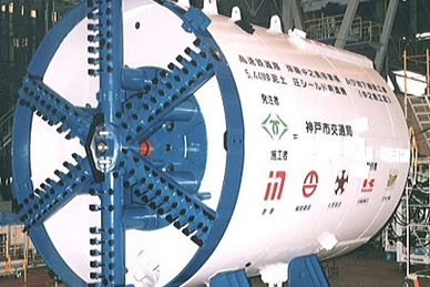
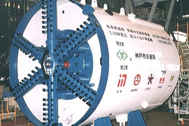
- Work name
- Kobe City Subway Kaigan Line Nakanoshima Stop
and Subway Line (Nakanoshima Section)
- Client
- Kobe City Transporation Bureau
- Construction period
- H7.11 to H12.12
- Work location
- Hyogo Prefecture
- Application
- Subway
- Outer diameter of the machine (m)
- φ5.44
- Work extension (m)
- 2484
-
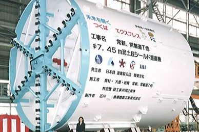
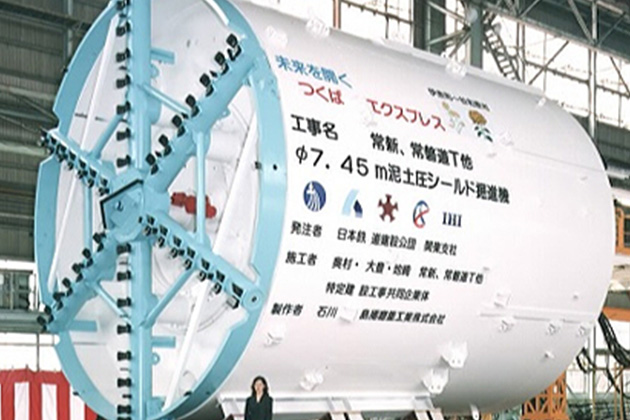
- Work name
- Work at Joshin, Joban Expressway T, etc.
- Client
- Japan Railway Construction Public Corporation
- Construction period
- H12.10 to H15.6
- Work location
- Ibaraki Prefecture
- Application
- Railway
- Outer diameter of the machine (m)
- φ7.45
- Work extension (m)
- 606
-

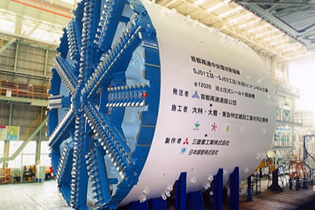
- Work name
- Section SJ51 to Section SJ53 (Outer Track)
Tunnel Construction
- Client
- Metropolitan Expressway Company Limited.
- Construction period
- H14.3 to H17.8
- Work location
- the Tokyo Metropolitan Government
- Application
- Road
- Outer diameter of the machine (m)
- φ12.02
- Work extension (m)
- 2018
-
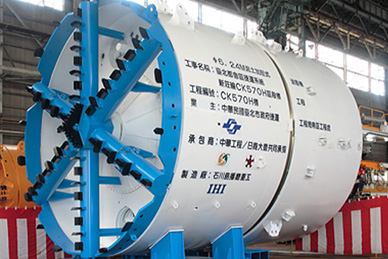
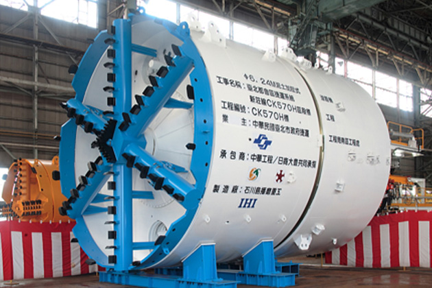
- Work name
- Taipei Subway Shinsho Line C570H
- Client
- Taipei City, Republic of China
- Construction period
- H15.7 to H24.3
- Work location
- Taipei City
- Application
- Railway
- Outer diameter of the machine (m)
- φ6.24
- Work extension (m)
- 2639
-
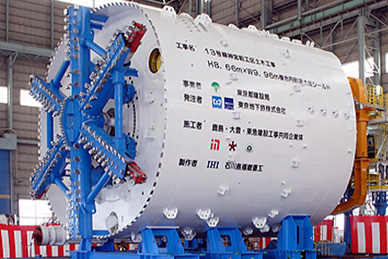
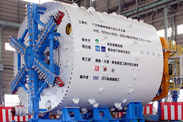
- Work name
- Civil Engineering Work in Route 13 Jingumae Section
- Client
- Tokyo Metro Co., Ltd
- Construction period
- H16.3 to H18.8
- Work location
- the Tokyo Metropolitan Government
- Application
- Railway
- Outer diameter of the machine (m)
- 8.66 x 9.96
- Work extension (m)
- 739
-
- Work name
- Akita Prefecture Omono River Sewage Work
(Marine Treatment Area)
- Client
- Akita Prefecture
- Construction period
- H17.5 to H21.3
- Work location
- Akita Prefecture
- Application
- Sewerage
- Outer diameter of the machine (m)
- φ2.28
- Work extension (m)
- 2091
-
- Work name
- Toyokawa Yosui 2nd Term Water Channel Attached to Seibu Kansen
Work in Togo Section
- Client
- Toyokawa Yosui General Operation Department, Japan Water Agency
- Construction period
- H19.5 to H21.3
- Work location
- Aichi Prefecture
- Application
- Water supply
- Outer diameter of the machine (m)
- φ2.49
- Work extension (m)
- 291
-
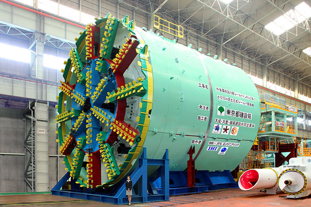
- Work name
- Central Circular Route
Shield Tunnel-2
- Client
- Bureau of Construction Tokyo Metropolitan Government
- Construction period
- H20.6 to H23.10
- Work location
- the Tokyo Metropolitan Government
- Application
- Road
- Outer diameter of the machine (m)
- φ12.53
- Work extension (m)
- 7967