


caisson
technology
technology
harbor technology
/green technology
- Mud pressurization (DK) shield method
- Double-O-Tube (DOT) shield method
- Developing Parallel Link Excavation (DPLEX) shield method
- Jack-driven Developing Parallel Link Excavation (J-DPLEX) shield method
- Detaching And Proceeding to dig Piping (DAPPI) construction method
- Mud pressurizing propulsion method
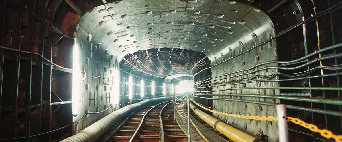
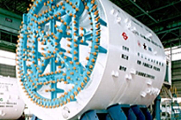
Civil Engineering Business: Developing Parallel Link Excavation (DPLEX) Shield Method
The shield method for building tunnels with arbitrary cut faces
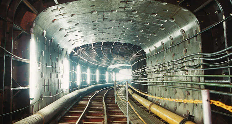
Outline of the construction method
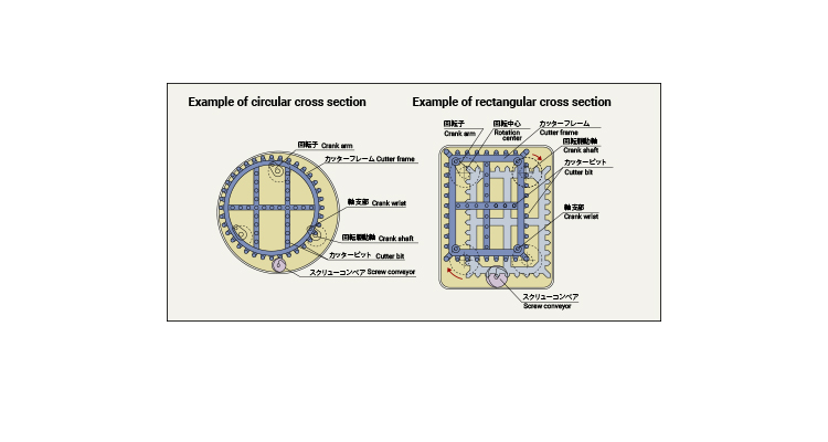
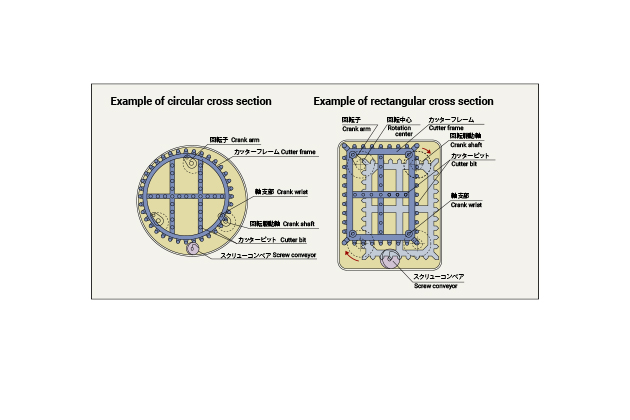
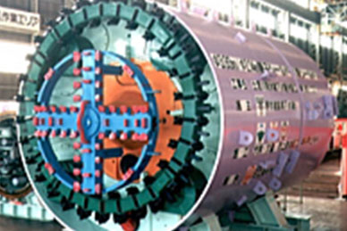
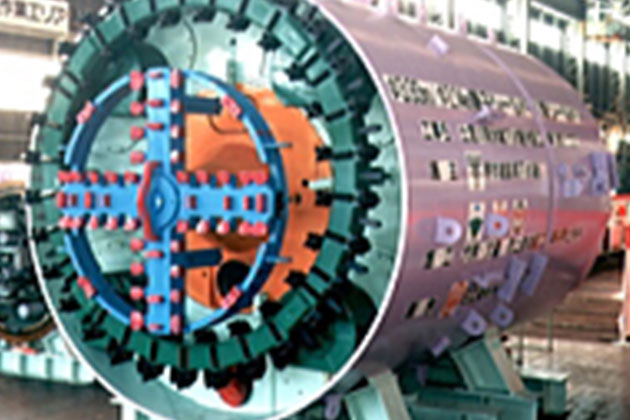
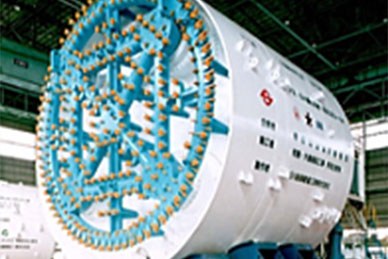
With the developing parallel link excavation (DPLEX) shield method, cutters are rotated by the parallel link mechanism mounted on multiple rotating shafts to excavate cross-sectional surfaces that are nearly the same figure as the cutter shape; therefore, it allows for the construction of tunnels with arbitrary cross-sectional surfaces other than circular shapes, such as oval and horseshoe shapes. Our employees took on the challenge of developing the world’s first square shield and demonstrated the outstanding achievement both internally and externally. As a result, the DPLEX shield method received the Technological Development Award by Japan Society of Civil Engineers in fiscal 1996.

Characteristics of the construction
method
By changing the shape of the cutter frame in case the upper and lower sides of tunnel are restricted by an underground structure or the site width is narrow, it is possible to choose an arbitrary cross-sectional shape suitable for the purpose, such as circular, rectangular, oval, and horseshoe shapes. Therefore, it is applicable even though there are limiting underground conditions, and it is able to use the underground effectively and economically.
With the small rolling radius of the cutter, the torque of the equipped cutter can be approximately 1/3 compared to the single-shaft mud pressurization shield, allowing for downsizing of the cutter driving device and reduction of output, which makes this method best suited for the shield of large-cross sectional surfaces.
Thanks to the small rolling radius of the cutter and the short sliding distance of the bit, all bits are worn equally and by only a limited degree. The amount of wear can be approximately 1/3 compared to the single-shaft mud pressurization shield; therefore, the work distance can be increased as much as about three times without replacing the bits.
By dispersing multiple shafts for driving the cutter, a large space can be ensured inside the machine; therefore, equipment for improving the ground, as well as the manhole, can be properly allocated. This makes it easy to perform ground improvement and remove obstacles.
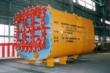
Since multiple cutter driving sections are designed as compact units, they are easy to transport, assemble, and disassemble, and the larger the cross-sectional surfaces, the more powerful the advantage becomes. Moreover, since equipment is designed as a small unit, and the work process is shortened, costs for the shield device, as well as work costs, can be reduced.
Our Works
-
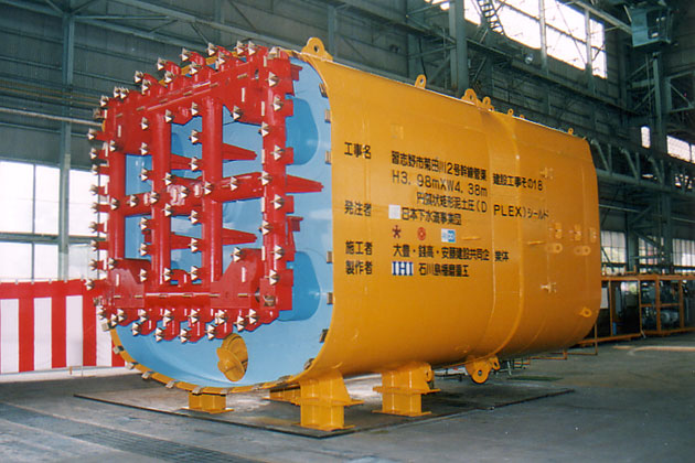
- Work name
- Narashino City, Kikudagawa No.2 Trunk Sewer
Construciton Work 18
- Client
- Japan Sewage Works Agency
- Construction period
- H6.2 to H8.9
- Work location
- Chiba Prefecture
- Application
- Sewerage
- Shape
- Arc-like rectangle
- Outer diameter of the machine (m)
- H3.98×W4.38
- Work extension (m)
- 392 417
-
- Work name
- MM, Honmachi Shield T Work
- Client
- Japan Railway Construction Public Corporation
- Construction period
- H10.3 to H13.2
- Work location
- Kanagawa Prefecture
- Application
- Subway
- Shape
- Circular
- Outer diameter of the machine (m)
- φ7.15
- Work extension (m)
- 452 432
-
- Work name
- Installation Work for Sewage Pipe of Doi River Rainwater Pipe
(2nd section)
- Client
- Sakai City
- Construction period
- H11.1 to H13.3
- Work location
- Osaka Prefecture
- Application
- Sewerage
- Shape
- Circular (Parent and Child)
- Outer diameter of the machine (m)
- Parent φ3.93 Child φ2.14
- Work extension (m)
- Parent machine 1,026 Child machine 751
-
- Work name
- Teito Rapid Transit Authority Route 11 Honjo Section
- Client
- Teito Rapid Transit Authority
- Construction period
- March 1999 to April 2001
- Work location
- the Tokyo Metropolitan Government
- Application
- Subway
- Shape
- Circular
- Outer diameter of the machine (m)
- φ9.60
- Work extension (m)
- 907